Making Wireless IoT Project Easy, Smart, Secure.
GET A FREE SAMPLEThe USB wifi module 5ghz is a device that connects the module with the computer, making the USB-Serial connection very simple and easy, without needing to use an FTDI and using complicated connections. Everything is quite simple, just plug it into the board and plug it into the USB.
The SKW71Wireless Module was specially developed. It helps to connect your microcontroller to a WiFi connection easily, efficiently and at a low price. This small and powerful WiFi SKW71 Module supports 802.11 b/g/n networks. Further, it is widely useful today, and can work as an Access Point (Access Point) or as a Station (Station), sending and receiving data.
In practice, the USB wifi module 5ghz is useful to connect your projects to wireless data networks. Here you can exchange information between microcontrollers, sensors or send them to a smartphone. Further, it prevents the presence of wires in your home, in this case of home automation projects.
The module's communication with the Arduino can be done via serial using the RX and TX pins, and can be configured through AT commands.
If you want to make the connection easier, we recommend the USB wifi module 5ghz Adapter which already has the level converter and can be connected directly to the breadboard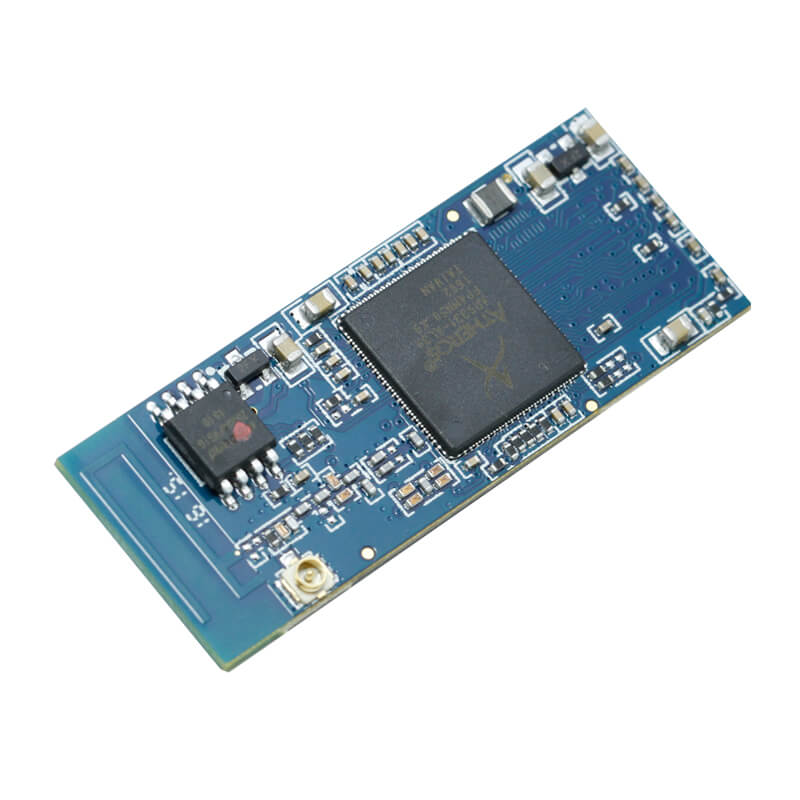
The project of the USB adapter was thought to make the connection of the module with the computer. So, that through a program that makes a serial communication RS232. The Termite is an example of software that makes this connection. From the factory yourSKW71 programs to work in AT command and through this adapter we can give commands for the ESP-01 to make various configurations.
But you can see that in this mode there is a problem that your module depends on another processor to do the tasks, functioning as a USB wifi module 5ghz of that other microcontroller. There is a mode, which is more interesting to use, which is using theSKW71 in Standalone. It makes it operate similar to an Arduino, with the advantage of being much smaller.
The downside is the small number of pins. But that might be enough for some projects. Without modifications to the USB adapter it is not possible to make the programs sending to the USB wifi module 5ghz. Furthermore, it is not possible to make it work in Standalone mode. Luckily, making these changes is simple and easy to do.
To record a simple program, we will need:
In order for the USB wifi module 5ghz to enter the UART program recording mode (serial), it needs that the GPIO0 pin is at a low level at its initialization.
Credit: theengineeringprojects.com
Therefore, the adapter cannot record programs. To make this adaptation, we will have to somehow make GPIO0 be at LOW level when the module starts up. For that, we can make a physical connection from GPIO0 directly to GND.
Thus, in order to control when the adapter must be in recording mode, we can place a seesaw switch connecting the GPIO0 pin and the GND pin so that in one position of the switch it is for recording programs, and in the other position the mode for monitoring and sending commands via RX/TX.
To make this adaptation, we can do it in two ways:
Resolution 1 – Directly soldering a wire to the adapter pins, where the soldering must be done carefully so as not to damage the USB wifi module 5ghz.
Resolution 2 - Or the other way to do it is to put a thin wire with a copper tip directly inside the female connector, like this:
It is important that the wire is really quite thin, and that the fitting needs to do delicately. So as not to damage any of the components OF USB wifi module 5ghz. Solder the see-saw wrench on the end of these cables.
To record the programs, put the seesaw switch in the ON position. And you will connect the module to the computer. If your Arduino IDE is not ready to handle SKW71 cards, open this tutorial and go to the “Procedures for installing NodeMCU in Arduino IDE” part, where it will teach you how to install SKW71based cards in your Arduino IDE.
And to take the reading, remove the adapter from the USB port, put the see-saw switch in the OFF position and plug it back into the USB. Open the serial monitor and observe the behavior of the program.
It is useful to connect your projects to wireless data networks. Moreover, making it possible to exchange information between microcontrollers, sensors or send them to a Smartphone.
Further, USB wifi module 5ghz prevents the creation of wire tangles in your home. It is important to note that the SKW71 Module uses a signal level voltage of 3.3V, and the RX pin cannot connect directly to the Arduino, under risk of irreversible damage to the module.
Therefore, for this connection it will be necessary to mount a voltage divider with resistors. We also advise that an external source must be good to power the module, since the consumption current in operation (up to 300mA) is greater than that supplied by the Arduino (50mA).
Ensure greater convenience in the development of your electronic projects, purchase the USB wifi module 5 GHz. It saves time in assembling your prototypes, in addition to providing better visibility, avoiding wires and wall breaks.
Conclusion
With this post we can see how to make a procedure so that theSKW71 USB adapter can be useful to send programs through Arduino IDE. With this, you can make programs. These are to control the pins embedded in theSKW71 board.
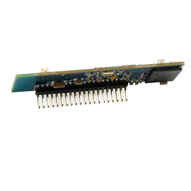
Moreover, if you consider its pin out, you can record programs to control GPIO 0, 1, 2 and 3. Similarly, you can take advantage of the Wi-Fi connection present in a simple way on the board.
Note: if you use pins 1 and 3, you will lose the serial connection with the computer, thus you will not be able to use the serial monitor. Take advantage and purchase the DIP Adapter so that the board fits perfectly into the breadboard, making your project easier.
Copyrights© Shenzhen Skylab Co.,LTD All Rights Reserved.


