Making Wireless IoT Project Easy, Smart, Secure.
GET A FREE SAMPLEwifi module mt7628: In the last 22 years, after the term “Internet of Things” was proposed, having as reference the digital interconnection of any physical objects with the internet, these objects being able to receive or send information to the network.
This project will explain in detail how to create a device to measure the level of a water reservoir with graduation from 20% to 20%, to present the results through a Web Server. And make the process of filling the reservoir automatically. 'water whenever it is below 20% of maximum capacity.
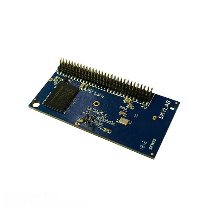
MT7628 Bluetooth 30-Pin Wi-Fi Module
This is the development board that will be common in the Wi-Fi module mt7628. Also, Using the most common programming for development boards: the Arduino IDE. This board was chosen for the attributions that make it essential for the project, such as:
Its function is to receive a digital signal from the system to act as a switch. Causing the microcontroller to turn on or off a higher power load, that is, a Wi-Fi module mt7628responsible for filling the reservoir, such as a hydraulic pump or a solenoid valve so as not to allow the reservoir to go below 20% (and empty) or above 100% (and overflow).
being normally open (NO), this way when it receives the signal it makes the connection. So that the want actuator works. There the normally close (NC), which is the opposite of the previous operation, when there is a signal, it breaks the circuit, causing the actuator to turn off.
For this project, there must be a 3.3V actuation relay, as the signal sent by the MT7628 board is 3.3V, or if you already have a 5V actuation relay, a bidirectional logic level converter needs to convert the signal from Wi-Fi module mt7628 to 5V, enabling the actuation of the 5V relay module.
project execution
The first step for the project is the configuration of the MT7628 board on the Arduino IDE platform. This action is only necessary for the first use of the module in Arduino IDE. If you don't have your board organized on the platform,
After connecting MT7628 and Arduino IDE, just copy and paste the code from this post. And configure your Wi-Fi module mt7628username and password as explained throughout the comments in the program.
After including the previous steps. Also, the program must be loaded in the MT7628 module, which when restarting and connecting to the Wi-Fi network is successful. The user must open the internet browser of their choice, either on the computer or on the cell phone.
And type the IP address number configure in the Arduino IDE, so that the Web Server show, which after the assembly of the circuit and the positioning of the capacitive touch sensors, will display on the screen the percentage of liquid in the reservoir.
The next step is the assembly of the circuit. It is important to emphasize that there are several versions of MT7628, being the module common in the project the Wi-Fi module mt7628WROOM32 DevKit.
To assemble the circuit, it is necessary to place 6 jumpers inside the water tank, 5 of which are for the connection of the MT7628 touch sensors to the tank. The sensors chosen for this task are those present in GPIO 13, 12, 14, 27, and 33. And the remaining jumper will serve as the reservoir's GND, however, they easy to modify in the programming according to the available ports.
To make contact between the jumpers and the internal part of the reservoir where the activation will be made (for illustration of this project), it was necessary to drill the places where the jumpers will insert. And, after insertion, it was necessary to seal with bicomponent epoxy putty (Durepoxi), but there are several other ways to get the triggering internally. The image below shows how the reservoir looks like.
after this step, it is necessary to position the 220R resistor leaving the GPIO 25 in series with the diffuse LED anode to signal the activation of the actuator, after this connection, just connect the LED cathode to the GND.
The actuation relay receives the signal via the wifi module mt7628 thus activating via the normally open (NO) connection, the actuator, which is the solenoid valve or the pump.
As shown in the system programming, the LED will be in the same state as the actuator, and as soon as the system presents the percentage of liquid level in the reservoir below 20%, the relay and LED are simultaneously activated until the reservoir reaches its maximum capacity (100%) and turn off.
Pins common in wifi module mt7628
To better guide you in the assembly, below you have the list of common GPIOs and their respective connections:
Conclusion
With this project, it is possible to be successful in several applications where it is necessary to automate or monitor the level of liquids in a reservoir in real-time at a distance, connected to the same network as MT7628, without an internet connection.
This control process is ideal for systems that use hydraulic pumps, as they wait for an emptying time before turning the system back on.
Copyrights© Shenzhen Skylab Co.,LTD All Rights Reserved.


