
Making Wireless IoT Project Easy, Smart, Secure.
GET A FREE SAMPLE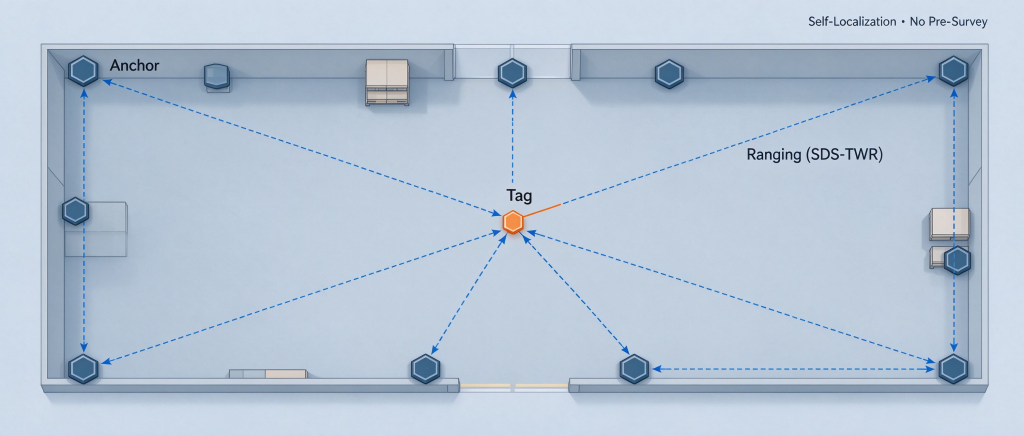
Why does deploying an industrial UWB positioning system cost so much more than the hardware? For most teams the hidden cost is not the anchors or the tags, it is the survey: someone has to walk the warehouse, tape-measure every anchor, and type those coordinates into the system. Get one coordinate wrong and the whole map is silently wrong.
Anchor self-calibration removes that step. The anchors figure out their own positions by ranging to each other, so a site can go from unpacking to a working map with no surveyor on site. SKYLAB’s zero-survey approach is built around this workflow: calibrate the anchors, solve the relative geometry, and fix the map with one or two reference points.
01 What does anchor self-calibration actually solve
Classical UWB deployment splits into two stages. First you place anchors and measure each one's coordinates with a laser distancer, a total station, or a floor plan. Then you run the positioning engine, which needs those coordinates to turn tag ranges into positions. The survey is the bottleneck: it is slow, error-prone, and every anchor moves during commissioning costs a re-measure.
Self-calibration (also called auto-localization or zero-survey setup) flips the order. The anchors use their own radio to range to each other, solve their relative geometry, and only need one or two known reference points to anchor the map to the building.
The payoff is real for industrial and warehouse sites: large open floor spaces, many anchors, and tight install windows. Cutting the survey step shortens commissioning from days to hours and removes the most common source of gross map error.
02 From pairwise ranges to a coordinate map
The core idea is simple: if every anchor can measure its distance to every other anchor, the set of distances contains enough information to reconstruct the relative geometry of the whole set.
Build the distance matrix. Let the anchors range pairwise and store the distances d_ij between anchor i and anchor j. For N anchors this gives an N × N distance matrix.
Reconstruct the layout. A technique called multidimensional scaling (MDS), or an equivalent least-squares solver, turns the distance matrix into a set of 2D or 3D coordinates that reproduce those distances as closely as possible.
Anchor to the building. Relative coordinates are not enough — the map can be rotated, translated, or even mirrored. One or two surveyed reference anchors (or a known baseline) fix the absolute position and orientation, removing that ambiguity.
That last step matters. Without a reference, a self-calibrated map is internally consistent but has no fixed relation to the room, so a tag position would be correct relative to the anchor set but wrong relative to the building.
03 The math: how a distance matrix becomes coordinates
Once you see how distances become coordinates, the accuracy requirements become clear.
For a pair of anchors, the squared distance is:
d_ij² = (x_i − x_j)² + (y_i − y_j)² + (z_i − z_j)²
where x, y, z are the anchor coordinates we want to solve for. Stacking all pairwise equations gives an over-determined system, solved by minimizing the sum of squared residuals between the measured and the reconstructed distances. MDS does this by eigendecomposition; a nonlinear least-squares solver refines the result and can fold in the known reference anchors as hard constraints.
The key insight: the accuracy of the solved coordinates is roughly the ranging error amplified by the geometry. Poor geometry — anchors clustered or nearly collinear — multiplies small ranging errors into large position errors.
04 Where the error comes from
Self-calibration is not magic; it moves the survey error into the ranging chain. The main sources:
Ranging error. Each anchor-to-anchor range inherits the same physical errors as any UWB range — antenna delay bias, crystal offset, multipath and NLOS. A fixed antenna-delay bias of a few centimeters on every link becomes a systematic distortion of the whole map.
Geometry (dilution of precision). A well-spread anchor layout keeps the error gain low; collinear or clustered layouts amplify errors in the weak axis. This is identical to the DOP problem in GNSS.
Reference ambiguity. If the reference anchors are mis-surveyed, the whole map is shifted or rotated by that same error. Self-calibration reduces, but does not eliminate, the need for accurate reference points.
Mirror ambiguity. Distance-only solving can produce a mirrored copy of the true layout. A known baseline or an external orientation reference disambiguates it.
05 When it fits: industrial and warehouse scenarios
Zero-survey deployment is not right for every site. It shines where the following hold:
Large, open, line-of-sight spaces. Warehouse floors, factory halls, and yards give anchors unobstructed views of each other, which is exactly what accurate anchor-to-anchor ranging needs.
Many anchors. The more anchors, the more redundant pairwise links, and the better the solved geometry. Self-calibration scales well with anchor count.
Frequent re-deployment. If anchors get moved for layout changes, seasonal zones, or temporary events, being able to re-run calibration instead of re-surveying is a big win.
A reference you can measure once. Even in zero-survey setups you still need at least one or two known points to fix the map to the building; the win is that you measure those once, not every anchor.
06 A reusable checklist for judging a zero-survey deployment
Before you choose: is the space line-of-sight between anchors? Can you install one or two accurate reference anchors? Is the anchor count high enough for good geometry? If any answer is no, a conventional surveyed install may be simpler.
During commissioning: calibrate antenna delay before self-calibration, run the solver, then verify by placing a tag at known points and comparing the reported position.
When evaluating accuracy: measure the error distribution (P50/P90) in the real environment, not the chip datasheet, and keep the worst-case NLOS cases as a statement of the system's ceiling.
The boundary: self-calibration is a deployment convenience, not a fix for bad physics. In a heavily obstructed, strongly multipath environment, accurate anchor-to-anchor ranging is itself hard, and the solved map inherits that. What self-calibration buys you is a faster, cheaper, less error-prone path to a good map — not a license to ignore the environment.
Copyrights© Shenzhen Skylab Co.,LTD All Rights Reserved.


